- TOP
- Additive Manufacturing Solution
Revolutionizing mold parts with the fusion of
existing technology and additive manufacturing
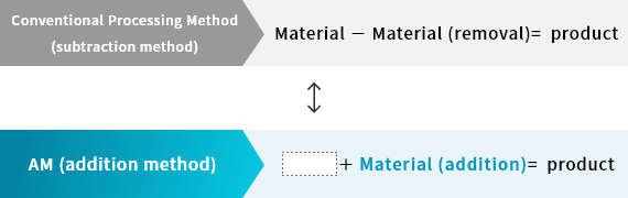
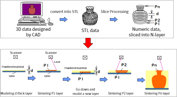
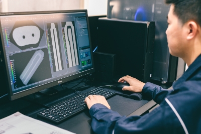
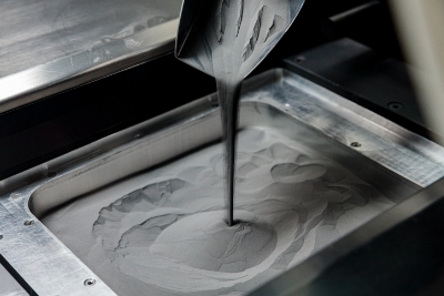
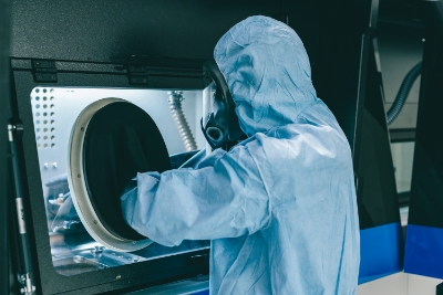
AM technology of 3D printing has allowed us to produce shapes we may never have imagined before. This new technology gives us more flexibility in the design of molds.
Our innovative technologies including conformal cooling, lattice structures, and molding integration push the limits of what is possible by integrating multiple components into one.
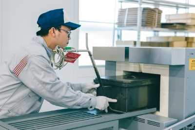
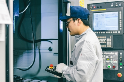
- Tooling Innovation
-
- Accumulated over 100 years of know-how and experience in mold manufacturing
- Designing products in a variety of industries such as automotive, motorcycles, and outboard motors
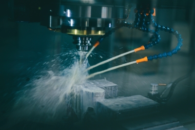
- Pursues the best metal cutting technologies
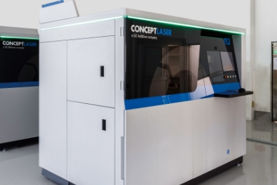
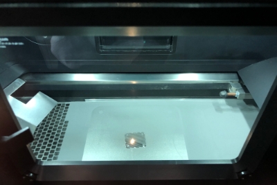
- Additive Manufacturing
-
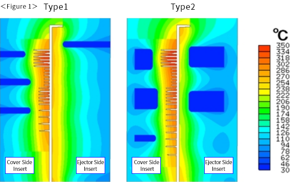
- Improved cooling performance with the use of conformal cooling
- Utilizing weight saving techniques through lattice structure and gas venting structure
- Lead time and cost reduction by integrating molding of multiple parts